
Corey Bailey
Audio Engineering
GLOSSARIES
ANALOG TAPE
A-Wind
Meaning; ‘Oxide in.’ An audio tape that has been wound in an
A-Wind, will have the tape oxide on the inside layers and the tape backing
towards the outside. This is how audio tape has been wound and delivered for
about 70 years.
Acetate tape
Acetate Tape refers to the material used as the base for
tapes manufactured from the early 50’s through the
1970’s. During the 1970’s, Polyester became the
preferred base material for analog tape. It’s worth noting
that each material has exhibited problems over time.
The acetate base becomes brittle over time. When
conditions are very dry, the tape can deform, causing a
condition known as ‘cupping’ and the tape will take the
shape of a metal Venetian blind. Too much moisture
during storage can cause a condition known as
‘vinegar syndrome’ in which the acetate base releases
acetic acid and the tape will have a vinegar odor.
FIG. 1 to the right, is an illustration of a typical tape
recorder head. The vertical line in the center
represents the head gap.
Azimuth
In the world of magnetic tape recorders, azimuth refers to the alignment of the
head gap relative to the direction of travel of the tape. This involves mainly the
record and playback heads however, on some tape machines, the erase head is
also adjustable.
The head gap represents the centerline of each head and should be precisely
90 degrees to the tape.
Any variation from 90 degrees will result in a loss of high frequency information.
Azimuth is one of the adjustable parameters of each head and there are specific
methods to check and adjust for the proper alignment.
B-Wind
Meaning; ‘Oxide out.’ During the dawn of analog tape recording, some tape
recorders used audio tape with the oxide facing out. In the early days of tape
recording, one could buy audio tape that was wound that way. Nowadays, a
B-Wind is sometimes used to reduce ‘Cupping’ on Acetate base tapes.
Back Coating
Many brands of professional polyester audio tape had a coating on the backside
of the tape (opposite the oxide). Many brands of audio tape had a back coating
that was electrically conductive. The back coating performs some important
functions;
1) The foremost purpose is to help prevent static buildup, which can cause arcing
and subsequent audible snaps in the recording.
2) While helping to eliminate static, the same back coating allows for more even
packing (winding) of the tape on the reel.
3) The back coating also serves as an insulating layer that helped prevent print
through, a condition in which the recorded magnetic field migrates from one layer
of the tape to another.
Bias
In a tape recorder, bias is a high frequency Alternating Current (AC) signal that is
applied to the erase and record heads during recording. The reason for the bias
signal is to magnetize the ferrous iron particles in the oxide in a manner which
provides the best linearity for recording. The frequency of the bias signal is
supposed to be at least 10 times the highest audio frequency capable of being
recorded by a given recorder (but rarely is). A typical bias frequency for consumer
recorders is anywhere between 40 kilohertz (forty thousand cycles per second)
and 100 kilohertz (kHz). Professional equipment can have a bias frequency
approaching 250 kHz. The fact is, anything that can be magnetized, does not
magnetize in a linear fashion. Early attempts to record without a bias signal, on
an oxide containing iron particles, resulted in poor frequency response. Applying
a DC (Direct Current) bias proved to be of little benefit.
The first patent for AC bias for use in electronics was filed by W. L. Carlson and
Glenn L. Carpenter in 1921. However, it was Walter Weber who employed the
technique of applying AC Bias to magnetic tape recording.
Binder Hydrolysis
This is a condition where the chemical binder in the oxide has absorbed moisture
over time to a point that causes a chemical change in the composition of the
oxide itself. This often results in Sticky Shed syndrome. Another variation in the
decomposition of the oxide results in a milky-colored stain on the surface of the
oxide that dramatically increases the friction during playback,
often causing the tape or magnetic film to come to a stop.
Coercivity
For magnetic tape, Coercivity refers to the strength of a given magnetic field
required to reduce the recorded magnetic field (signal) on the tape to zero after
the oxide has been driven into saturation. Tapes using an oxide with greater
coercivity, generally require a stronger Bias signal.
Capstan
On a tape recorder, the Capstan is the rotating vertical shaft that pulls the tape
past the heads. The tape is usually squeezed between the Capstan and a
rotating wheel known as the Pinch Roller.
Degausser
A device that emits a strong enough Alternating Current magnetic field to
completely erase magnetic media or magnetized metal parts and tools.
Demagnetization
Simply stated: “The process of removing magnetism from any material that can
be magnetized.” In tape recording, tapes are demagnetized by being exposed to
an AC field strong enough to overcome the coercivity of the tape. On audio tape
decks, this process is accomplished by the erase head during recording.
Also on audio tape decks, the metal parts that come in constant contact with the
tape (particularly, the tape heads themselves) can become magnetized over time
and have to be demagnetized using a portable degausser.
The process of demagnetizing the heads and various parts of a tape deck has its
own learning curve. If done improperly, one can actually magnetize the intended
parts and cause harm to tapes that are subsequently played on that machine.
Dropout
A dropout is a brief loss or sudden decrease of signal level (volume), most often
caused by a defect in the tape oxide. Dropouts can also be caused by damage to
the tape itself, a temporary clogging of the record head during recording, or
likewise, a clogging of the play head during playback. Tape oxide defects can
cause frequency-selective dropouts, such as a brief loss of high frequency
information. Tape speed can be a factor in the effect of tape-defect related
dropouts as the condition is less noticeable at higher tape speeds.
Dynamic Range
In the world of audio, Dynamic Range is defined simply as the range of volume
from the loudest to the softest of sounds. Dynamic Range is expressed in
decibels (dB) which is a logarithmic scale.
We Recording Engineers, often refer to Dynamic Range in terms of the difference
between the loudest undistorted signal that be recorded down to the noise level
(floor) of a given medium. Analog tape is capable of a dynamic range of roughly
70dB. A Compact Disk (Audio CD) has a theoretical dynamic range of 96dB. The
average human can hear a dynamic range of approximately 140dB.
Erase Head
The erase head on an analog tape recorder is self explanatory, it erases tape!
It does so by being energized by the bias oscillator with enough voltage and
current to saturate the tape with the bias frequency.
The erase head is usually only energized during recording. The erase head
is also the first to come on contact with the tape during recording. If you view the
heads of a reel-to-reel tape deck straight on, the erase head will be on the left.
Flanging
Flanging is an effect that was originally created by using two analog tape decks
playing the same material in sync with each other. The operator would put gentle
pressure on the supply reel of one of the tape decks, causing the speed to
change slightly. The resulting speed change caused random parts of the signal to
react with each other and the result was recorded. Because this process is phase
related, it was often known as ‘Rubbing.’ It didn’t take long for hardware to appear
on the scene, eliminating one of the tape decks. The signal was played through
the hardware and all the operator had to do was turn a knob to achieve the
desired effect. Now, the effect can be created digitally with software.
Flutter
Tape recorders are designed to pass the tape across the heads at a very
constant speed. Any changes in the tape speed of a pre-recorded signal are
perceived as changes in pitch. If these speed changes occur very rapidly, the
effect is a ‘fluttering’ sound. Hence, the term. Flutter can be caused by something
as simple as a piece of tape that becomes inadvertently wrapped around the
capstan or a very worn pinch roller.
A type of tape degradation known as Sticky Shed Syndrome can cause flutter as
the tape itself tends to chatter across the heads.
Guides
Tape guides are generally stationary posts that are placed very near the heads to
keep the tape in proper vertical alignment. Worn guides can not only loose their
ability to keep the tape properly aligned but can actually damage tape as it is
passed across them.
Heads out
Holding a reel of audio tape in front of you, the tape will un-spool from the left.
In order to indicate the state of the tape, the loose end is usually folded and
fastened to the reel with adhesive paper tape in such a manner that the folded
and taped end will face the operator when the reel is placed on the machine
(or a table, for that matter). This makes it easy to identify which way to mount a
given reel of tape onto the tape deck.
IPS (Inches Per Second)
The linear speed of the audio tape as it is played on the tape deck. Tape speeds
vary from as slow as 15/16 IPS to as much as 30 IPS for analog tape machines.
Reel-to-reel digital audio tape machines will typically operate at a greater speed.
Generally speaking, for analog tape, the faster the tape speed the better the
sound quality. Tape speeds of 3-3/4 & 7.5 IPS were common for consumer tape
recorders and professional machines typically operated at 15 & 30 IPS.
Leader
Audio tape leader is a paper or plastic product cut the same width as the tape.
Leader is used to separate specific segments of audio tape, such as each song
on music masters. Leader is typically added to the beginning of a reel and often
to the end of a reel of tape. Leader that has been applied to both ends of an
audio tape will protect the first couple of wraps of the tape at the head and protect
the tape from the threading slots on the center of the reel at the other end. Some
manufactured tape comes with leader already attached to the tape. Some plastic
leader is printed with markers for every second of time and is called: ‘Timing
Leader’
Library wind
This is a process whereby the tape is wound from one reel to the other at
reduced tension and at a speed that is much slower than full rewind speed.
Typically, around 45 IPS. This results in a very even wind on the take-up reel, and
a tails-out configuration which, is desirable for long term storage.
Lifters
The tape lifters are vertical posts that usually reside near the heads of a tape
recorder and are energized during fast-forward or rewind. During this process,
the lifters move the tape away from the heads to prevent wear during the high
speed shuttling of the tape. Know that the tape lifters are usually stationary while
the precious oxide is whizzing past and in direct contact with them.
Noise Reduction
Numerous articles and books have been written on this subject, and it is difficult
to summarize Noise Reduction in a few sentences. When it comes to analog tape
recording, there are two basic approaches:
Single-Ended and Dual-Ended.
Single-Ended systems generally deal with tape hiss and other anomalies after
the fact or after the recording is made. Today’s digital editing software is often
designed to be able to improve upon recorded anomalies after the fact and is a
good example of a ‘single-ended’ approach. A number of hardware devices were
made during the analog era for single-ended noise reduction by companies like
Burwen, DBX, Phase Linear, SAE, etc. and can still be found on the vintage
hardware market. These hardware devices work in ‘real time,’ meaning that the
recorded audio has to be played through them for processing.
Dual-Ended noise reduction involves processing the audio signal before and
after recording. Ray Dolby first applied this process in 1966 with the introduction
of Dolby A type noise reduction intended for use with professional audio tape
recording. Dolby Laboratories subsequently introduced noise reduction
processes for the consumer market and became a household word.
Besides Dolby Laboratories, DBX and Telefunken produced very effective dual-
ended systems that were used in both professional and consumer recording.
Oxide
This is the composition that has been applied to the side of magnetic tape that
contains the magnetic recording. Oxide consists of a slurry containing the metal
particles, a binder solution which, helps adhere the oxide to the backing,
lubricants to make the dried solution both flexible and less physically noisy when
passing across the heads, and several other chemical compounds.
The actual chemical composition of oxide remains a closely guarded secret by
the various manufactures of magnetic tape.
Pinch Roller
The Pinch Roller (sometimes referred to as a ‘puck’) on a tape deck is that round
wheel that presses the tape against the capstan to move the tape across the
heads. Pinch rollers are free-wheeling and are usually made of rubber or a semi-
soft composite material.
Playback Head
If you were able to view the construction of a play head, it would look somewhat
like a horse shoe with several turns of fine wire wrapped around it.
The tape is pulled across the gap of the horse shoe shape.
The actual gap is tiny (microns, in fact) in order to concentrate the magnetism
that has been imparted onto the tape by the record head.
See FIG. 1 for an illustration of a tape recorder head. If you view the heads of a
reel-to-reel tape deck straight on, the play head will be on the right.
Play Wind
This is how the tape winds up on the take-up reel after being played from left to
right. A ‘Play Wind’ is considered to be desirable for long term storage.
The reason is that if print through occurs, the print-through information will be
after the recorded audio and be masked or sound like echo.
If the tape is stored heads-out, the print-through information can precede the
recorded audio on the tape and is known as ‘pre-echo.’
Polyester tape
This refers to the type of base material used for audio and video tape.
Polyester, sometimes referred to as PET, is a substance known scientifically as
Polyethylene Terephthalate. (I can’t pronounce it well either!)
Polyester back tapes are known to have problems when the oxide absorbs
moisture over time. This usually causes a condition called Sticky Shed Syndrome
(SSS). Layer to layer adhesion problems can sometimes happen.
When this happens, the unfortunate result is that the oxide can separate from the
base and stick to the preceding layer of tape or literally fall off in some instances.
That condition is generally unrepairable.
Print Through
When audio tapes are tightly wound on a reel and/or stored for extended periods
of time, the adjacent layers can sometimes influence each other. That is, one
layer can partially magnetize an adjacent layer. This condition can be more
predominant if the recorded levels are extremely loud or ‘hot,’ non back coated
audio tape or with thinner varieties of audio tape. The use of conductive back
coatings on many brands of audio tape helped alleviate this condition. If the tape
is wound heads-out, the partial magnetization will sound like pre-echo. This is
one of the reasons for storing audio tapes tails-out. If print through occurs in a
tails-out wind condition, it is either masked or sounds more like natural echo. It
has been recommended by some that stored audio tapes be periodically rewound
and stored again, using a play wind or preferably, a library wind. Periodically
rewinding audio tape is a very labor intensive process which,
in practice, is rarely done.
Record Head
The main difference between a record head and a playback head is the size of
the gap between the poles of the head itself. We’re talking microns here.
However, the gap on a record head is typically wider than that of a playback
head. See FIG. 1 for an illustration of a tape recorder head. If you view the heads
of a reel-to-reel tape deck straight on, the record head will be in the center of a
three head tape deck.
Round Robin
This is an effect that causes a repeating of the signal. It is actually a type of
feedback that is created by playing the signal into a mixing console and assigning
the signal back unto itself. Nowadays, the effect can be created digitally with
software.
Saturation
This is the state reached with magnetic tape when the oxide has been
magnetized to the point where it cannot be magnetized any further. Exceeding
this threshold with an alternating current magnetic field (via the record head) will
cause the magnetic particles in the oxide to become disoriented, and audible
distortion occurs.
Signal-to-Noise Ratio
In engineering or scientific terms; Signal-to-noise ratio refers to the strength of a
given signal in relation to the background noise associated with that signal.
Signal-to-Noise Ratio can be applied to everything from astronomy to video to
analog & digital audio recording. It is often abbreviated as SNR or S/N.
Recording engineers will sometimes increase the signal-to-noise ratio of analog
tape by increasing the reference level of the recording. The overall increase is
small but often noticeable, depending on the material.
Sticky Shed Syndrome
Abbreviated SSS, this condition is particularly damaging to the tape being played.
It’s a condition whereby the binders and lubricants in the oxide have absorbed
enough moisture over time to cause the oxide to become soft. When played on a
tape recorder, the characteristic symptom is often a squealing or squeaking
sound which modulates the audio being played. The tape will often shed oxide on
all of the stationary parts of the tape deck. The accepted but temporary, fix is to
carefully bake the tape under controlled conditions.
The Digital Audio Tape formats have recently shown signs of SSS so, if you own
any of these, now is the time to inspect them. Unfortunately, these formats will
typically not show a problem until they are played and, then it can be too late for
your prized digital audio recorder. (Particularly the rotary head formats)
Sound-on-Sound
An effect (sometimes a mistake) whereby a signal is recorded onto an existing
recording. When played back, both signals can be heard but not separated.
This process is made possible by disabling the erase head when applying the
second signal to an existing recording.
Tails-out
Holding a reel of audio tape in front of you, the tape will un-spool from the right.
In order to indicate the state of the tape, the loose end is usually folded and
fastened to the reel with adhesive tape in such a manner that the folded and
taped end will face the operator when the reel is placed on the machine or any
flat surface. This makes it easy to identify which way to mount a given reel of tape
onto the tape deck.
Tape Baking
The process of baking analog tape involves raising the ambient temperature of
the tape to 120 - 130 degrees Fahrenheit (48.8 – 54.4 degrees Celsius) in a very
low humidity environment for specific amounts of time based on the width of the
tape, the thickness of the tape and the size of the reel. The process was first
proposed (even patented) by AMPEX Corporation in the early 1990's.
This procedure can only be applied to Polyester base tape.
Acetate base tape can be damaged by this process.
VSO
VSO stands for Variable Speed Oscillator. A VSO is used on a an analog tape
recorder that has a DC capstan motor to vary the speed of the tape. Some
recorders had a speed control built in and others required an external device.
Tape recorders that use an AC sync motor as the capstan motor, are generally
not speed controlled.
Wow
The sudden change of pitch of a recorded signal caused by physically altering the
tape speed for a very short duration of time. The reasons for the occurrence can
be everything from mechanical failure of the tape recorder, to tape damage. Wow
can also be created purposely by applying enough pressure to the supply reel
during playback to momentarily alter the tape speed.
Zenith
On an audio tape recorder, Zenith refers to the relationship of the vertical
alignment of the face of each head and the tape guides to the deck plate or
mainframe in order to provide even contact over the entire surface of the tape.
Zenith, like Azimuth, is usually an adjustable parameter of each tape head.
References
Howard M. Tremane, “Audio Cyclopeia” Second Edition, Howard W. Sams, 1973
Rudolph F. Graf, “Dictionary of Electronics” Howard W. Sams, 1974
Glenn D. White, “The Audio Dictionary” University of Washington Press, 1987
Dr. John W. C. Van Bogart, “Magnetic Tape Storage and Handling” National
Media Lab, 1995
Wikipedia, http://www.wikipedia.org/
Return to TOP of page
© Corey Bailey Audio Engineering


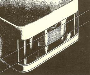
FIG. 1
This image is from the
inside of a Scotch 111
tape box. (Acetate base)


