Corey Bailey
Audio Engineering
GLOSSARIES
GENERAL TERMS
5.1 Channel Audio
This is a listening environment that involves the use of six separate speakers.
The placement configuration is: Left, Center, Right, Left Surround, Right Surround
and a Subwoofer. The left, Center and Right speakers are placed
in front of the listener and the Left and Right Surround speakers are placed
to each side or slightly to the rear of the listener. The Subwoofer is generally
placed somewhere to the front of the listener. The exact placement of the
Subwoofer is dependent on its individual design and the acoustics of the listening
room.
The term ‘5.1’ refers to the individual channels with the ‘.1’ referring to the
Subwoofer since its bandwidth is limited to the lower part of the audio frequency
spectrum.
This concept has been greatly expanded upon and now includes;
Rear Surrounds, Overhead speakers and the whole package is known as
Immersive Audio.
AM
This is an abbreviation that stands for Amplitude Modulation. We all know what
AM Radio is (at least, in the U.S.A.), but understanding what Amplitude
Modulation is will take some explanation;
Radio transmission involves a frequency called a Carrier Frequency.
This carrier frequency is demodulated (eliminated) by your receiver.
When you tune a radio receiver to a station, you are actually tuning in a carrier
frequency to demodulate.
In the case of AM radio, the carrier frequencies used are in the Kilohertz range
(100,000 cycles per second).
Amplitude Modulation simply means that the carrier frequency is modulated by
the amplitude (volume) of the signal being transmitted. Once your radio receiver
strips out the carrier frequency, what’s left is the audio signal being transmitted.
The number used to tune the station is representative of the carrier frequency
used by that particular radio station. XYZ 950 would mean that the AM radio
station XYZ is transmitting with a carrier frequency of 950 Kilohertz (kHz).
Clipping
Audio, as we know it and are used to hearing it, consists of symmetrical sine
waves whether it’s a clarinet, a cricket, or a cymbal crash. Whenever the volume
of undistorted audio is increased beyond the limit of a given piece of electronic
equipment or a medium such as digital recording, the nice round tops of those
sine waves are flattened or ‘clipped off.’ The result is very noticeable.
dB
dB is the symbol abbreviation of a decibel. The decibel is a unit of measurement
that is one tenth of a bel, which itself, is a unit of measurement that is seldom
used.
Decibel calculations are made using a logarithmic scale.
For example;
A change in power ratio by a factor of TEN is a 10 dB change.
A change in power ratio by a factor of TWO is approximately a 3 dB change.
The bel and the decibel originated at Bell Telephone Laboratories as a unit of
measurement for the signal loss (or gain) in telephone circuits. The bel was
named for the founder of Bell Telephone, Alexander Graham Bell. It’s worth noting
that Bell Telephone Laboratories established the ground rules and practices that
have been used by professional audio installations since the early part of the
twentieth century and are still in use today.
There are a few flavors of dB in use. Some examples are;
dBm (The ‘m’ for milliwatt) is a measurement of power where ‘0’ dBm equals one
milliwatt of power.
0 dBm is 0.775 Volts RMS referenced into a 600 ohm resistor or load.
dBu In this case, the ‘u’ stands for unterminated or unloaded. 0 dBu is 0.775
Volts RMS that is not referenced into a given termination or load.
dBV This signifies a reference level of 1 volt RMS, regardless of the load and
thus, will vary as the load (or resistance) varies.
DBFS This is actually a definition as opposed to a reference level.
It refers to the decibel level below ‘0’ VU, full scale. It came about with the advent
of digital recording where the absolute maximum level is 0VU or full scale digital.
The professional audio standard most often used for digital audio recording is;
-20DBFS which is a reference level of 20dB below full scale digital or 0VU.
Feedback
Most commonly associated with that bone jarring, teeth rattling howling and
screeching that occasionally happens at live venues when the volume of a
particular microphone is turned up too high or the microphone itself is placed too
close to one of the PA speakers. This is known as acoustic feedback and it
happens because microphones are very sensitive to small changes in
atmospheric pressure while speakers are designed to effect very large changes in
atmospheric pressure. When a particular speaker is reproducing the amplified
output of a microphone, feedback can happen when the microphone is placed in
close proximity to the speaker because, in effect, you’ve created a closed loop.
Ironically, feedback at the electronic component level is what makes all this
possible. In the world of electronics, amplifier gain is controlled by routing a small,
carefully controlled, amount of the signal from the output of an amplifier back to
its input……Feedback!
FM
The abbreviation for Frequency Modulation, FM is the household acronym in the
U.S.A. that refers to the commercial radio band which is broadcast using a carrier
frequency between 87.5 and 108 Megahertz (millions of cycles per second or
MHz). The 87.5 to 108 MHz band is common throughout the world with a couple
of exceptions; Japan and Russia, where a wider frequency spectrum is used.
Frequency Modulation is accomplished by modulating the carrier frequency with
the frequencies of the signal being transmitted. When you tune a radio receiver to
a station, you are actually tuning in a carrier frequency to demodulate.
Once your radio receiver strips out the carrier frequency, what’s left is the audio
signal being transmitted.
An interesting benefit of FM radio transmission is that the noise power decreases
as the signal power is increased. Thus, a 50,000 watt transmitter will have a
better signal-to-noise ratio than a 10,000 watt transmitter.
Harmonic Distortion and Total harmonic distortion (THD)
Harmonic Distortion is a consequence of electrical amplification.
The actual harmonic component measured at the output of an audio amplifier is:
Total Harmonic Distortion plus Noise (THD+N).
First, we need to understand just what a harmonic is;
A harmonic is any frequency that is a multiple or a product of a fundamental
frequency.
Imagine a guitar string. If you pluck the string exactly in the middle, it vibrates at
its fundamental frequency plus a second harmonic frequency resulting from the
string being divided in two when plucked. Each half of the string also vibrates at
the same time as the full length string is vibrating, creating a second harmonic,
which, in this case, is twice that of the fundamental frequency.
All electronic amplifiers create harmonics of the fundamental frequencies being
amplified. The type and amount of harmonics generated are a consequence of
amplifier design and the amount of amplification involved. When the harmonic
distortion of an amplifier is measured, a pure tone is applied to the input of the
amplifier by a piece of equipment known as a distortion analyzer (makes sense).
The output of the amplifier being tested is fed back to the distortion analyzer,
which removes the pure tone, measures what's left, and usually displays the
results in decibels. Some distortion analyzers do the math and display the results
as a percentage. The displayed results are all of the harmonics generated by the
amplifier plus any noise added by the process of amplification.
Total Harmonic Distortion + Noise.
Hertz (Hz)
No, this is not about the car and truck rental company. Hertz, abbreviated Hz,
represents the definition of frequency. Frequency, in this case, is referring to
cycles per second (CPS). Hertz is the surname of Heinrich Hertz, a German-born
PhD physicist who, in the late Nineteenth century, was able to conclusively prove
the existence of electromagnetic waves.
The most common multiples of Hertz are:
Kilohertz, is one thousand cycles per second (kHz).
Megahertz, is a million cycles per second (MHz).
Gigahertz, is one billion cycles per second (GHz)
Intermodulation Distortion (IMD)
This gets a little more complicated than harmonic distortion because IMD is the
byproduct of non-linear amplification and is not harmonically related to the signal
being amplified.
As an amplifier creates harmonics of the fundamental signal, some of those
harmonics themselves create sum and difference frequencies. This process is
called….you guessed it!….intermodulation. Those frequencies created by the
process of intermodulation are measured as intermodulation distortion. Using a
distortion analyzer, IMD is measured by feeding two pure tones into the amplifier
under test, subtracting them at the amplifier’s output, and measuring what’s left.
An aside;
All types of distortion are cumulative. Each time the signal is processed, the
overall distortion is increased, regardless of the type of signal.
Loudness Control
The switch on your stereo system that compensates for the apparent loss of bass
and treble at lower volume settings.
Our hearing is level or loudness dependent. As volumes decrease below normal
speaking levels, we tend to loose sensitivity at the lower and higher frequencies,
leaving only the midrange (2-5 kHz) which curiously, is where most of the energy
of the human voice resides. Two researchers with the surnames of Fletcher and
Munson, documented this phenomenon in the 1930’s.
Their findings resulted in what is known as the Fletcher-Munson curve.
The loudness control on your home audio equipment is designed to create what
is known as an equal loudness contour that compensates for our level-dependent
hearing.
Minus 10 (-10)
Technically speaking, Minus 10 is 10 dB below the reference point of 0 dBu.
So, what is 0 dBu you ask? 0 dBu is 0.775 Volts RMS not referenced into a given
termination or load.
That said, Minus 10 dBu, is actually the ‘0’ reference level for most consumer
analog equipment. The reference voltage (for those still interested) is 316
millivolts (Mv) or 0.316 Volts.
MONO or: Monaural
Defined simply as ‘single-channel.’
Although there was some early experimentation with stereo recording, nearly all
of the records produced from the beginning of recorded sound up through the
middle 1950’s were monaural.
Peak Music Power
More of an advertising slogan than an actual reference measurement.
Peak Music Power is measured with an amplifier operating at 100% power.
And, this is assuming 100% efficiency, which few production model amplifiers can
achieve. In this case, the peak power rating is referring to the maximum output
power that can be achieved for an instant without destroying the amplifier under
test. Manufacturers will often connect the amplifier under test to a very large,
“brute-force” power supply in order to measure the maximum peak output rating.
Obviously, this is not practical or even sustainable. Manufacturers love this rating
as it typically overrates the product by about 30%.
Pink Noise
Yes, some types of noise are defined by color. Pink Noise is all of the frequencies
combined within a given spectrum. And, all of those frequencies within that given
spectrum have the same power. The spectrum for Pink Noise used in the audio
realm is usually 20Hz to 20kHz. Pink Noise is useful for measuring how flat (or
equal) the frequency response is of a given piece of audio equipment. Pink Noise
was routinely used for calibrating analog recorders. It takes a specially designed
generator to produce Pink Noise, and, in order to view it in real time, a spectrum
analyzer must be used. Pink Noise sounds somewhat like a waterfall. The sound
of a waterfall (up close) would be defined as white noise, or all of the frequencies
combined not within a given spectrum but usually of equal power. There are
actually several noise colors.
Quadraphonic
This is a discrete 4 channel system that consists of 2 front channels and 2 rear
channels. Quad, as it was known, was actually introduced with 4 channel
reel-to-reel audio tapes in the late 1960’s. By the early 70’s Quad formats started
appearing for vinyl record albums. Eventually, there were three competing
Quadraphonic formats for records, and the resulting confusion in the consumer
market may have led to its ultimate commercial failure. One of the formats, the
Sansui QS system, (regular matrix) was resurrected by Dolby Laboratories
in the mid 1970’s and was successfully used as a theatrical sound format for
feature films. It’s known as ‘Dolby Stereo.’ Dolby reassigned the audio channels
to; Left, Center, Right and one Surround channel. This is the analog format that
still survives on today’s feature film release prints.
R.M.S.
An abbreviation for the term ‘Root Mean Square.’ This mathematical formula is
useful for calculating the statistical average of a given quantity. It is used in
several scientific disciplines such as the physical sciences, statistics, and
electronics. In electronics, the RMS formula is used to measure an audio power
amplifier’s ability to provide continuous power into a given load such as your
speakers. The RMS power rating of a power amplifier is achieved using a single
tone that is fed into the amplifier input at a specified voltage while the amplifier is
terminated into its designed load. The signal at the output is measured using a
meter calibrated to measure RMS voltages. The RMS rating of an amplifier is the
power rating that matters most because it tells you the power that can be safely
and continuously delivered to your speakers.
If the manufacturer’s specifications do not include the RMS power rating, you can
closely calculate it by multiplying the advertised peak power rating by 0.707.
WATT-HOUR
An energy expenditure of 1 Watt-hour represents 3,600 joules or 3.600 x 10³ J.
A Watt-hour is expressed as Wh. A joule is expressed as the symbol J.
To obtain joules when the watt-hours are known, multiply the number of watt-
hours by 3.600 x 10³. To obtain watt-hours when joules are known,
multiply the number of joules by 2.778 x 10⁻⁴.
Your electrical bill is usually expressed in Watt-hours so, it’s worth knowing.
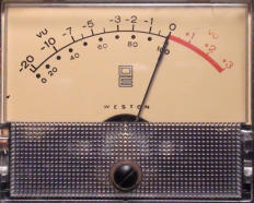
VU
The abbreviation for ‘Volume Unit.’
The VU meter is a reference meter
calibrated in decibels. ‘0’ VU on a VU meter originally corresponded to 0 dBm, or
0.775 Volts RMS referenced into 600
ohms.
In professional audio,
‘0’ VU is often +4 dBu.
Which is; 1.23 volts RMS at 1000 Hz.
The VU meter was introduced in the late
1930's and originally contained two
scales; dB on the top scale and
‘percentage of modulation’ on the lower
scale, calibrated from 0 to 100. The percentage of modulation was a useful
reference for the broadcast and feature film industries.
Rferences
Howard M. Tremane, “Audio Cyclopeia” Second Edition, Howard W. Sams, 1973
Rudolph F. Graf, “Dictionary of Electronics” Howard W. Sams, 1974
Glenn D. White, “The Audio Dictionary” University of Washington Press, 1987
Wikipedia, http://www.wikipedia.org/
Return to TOP of page
© Corey Bailey Audio Engineering